
When I want to draw graph-like pictures I almost always use dot from the graphviz suite. The language is simple and it’s easy to generate it programmatically. Still, I don’t do it every day and so I always have to do a quick review of the language to draw my picture.
The other day, while I was looking for something completely different, I came across this wonderful tutorial by Karl Voit on Org’s Worg site. In it he shows how to leverage a bit of Elisp code from Rick Frankel to produce dot diagrams from a couple of tables. The idea is that you list the nodes of the graph in one table and the edges in the other and the code runs dot for you to produce the PNG file.
The examples that Voit uses doesn’t do his tutorial justice because they involve producing flow charts and who wants to do that? Not me, at least. I almost always either want a tree of some sort or perhaps a state diagram. So here are a couple of examples that show how easy it is to use the code and techniques he describes to draw those objects. Be sure to read the tutorial so you can follow along with the examples.
 1: (org-babel-execute:dot
 2:  (concat
 3:   "digraph {\n"
 4:   (when horiz "rankdir=LR;\n")       ;up-down or left-right
 5:   (mapconcat
 6:    (lambda (x)
 7:      (format "%s [label=\"%s\" shape=%s style=\"filled\" fillcolor=\"%s\"]"
 8:              (car x)
 9:              (nth 1 x)
10:              (if (string= "" (nth 2 x)) "box" (nth 2 x))
11:              (if (string= "" (nth 3 x)) "none" (nth 3 x))
12:              )) nodes "\n")
13:   "\n"
14:   (mapconcat
15:    (lambda (x)
16:      (format "%s -> %s [taillabel=\"%s\"]"
17:              (car x) (nth 1 x) (nth 2 x))) graph "\n")
18:   "}\n") params)
I’ve reproduced the code here because I made a small tweak in line 4 so that I can produce both horizontal and vertical layouts with the same code block. With the code in the tutorial you have to uncomment code to get the horizontal layout. To use my code you should change the HEADER line to
#+HEADER: :var nodes=simple-tree-nodes graph=simple-tree-graph horiz='nil
for vertical layout or
#+HEADER: :var nodes=simple-tree-nodes graph=simple-tree-graph horiz='t
for horizontal layout. The horiz variable can be changed in #+CALL statements so that you can have both modes in the same file.
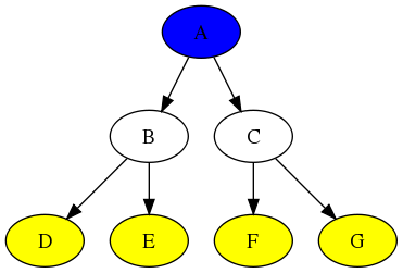
Here’s a simple tree with a blue root, white internal nodes, and yellow leaves.
| node | label | shape | fillcolor |
|---|---|---|---|
| a | A | ellipse | blue |
| b | B | ellipse | none |
| c | C | ellipse | none |
| d | D | ellipse | yellow |
| e | E | ellipse | yellow |
| f | F | ellipse | yellow |
| g | G | ellipse | yellow |
| from | to | label |
|---|---|---|
| a | b | |
| a | c | |
| b | d | |
| b | e | |
| c | f | |
| c | g |
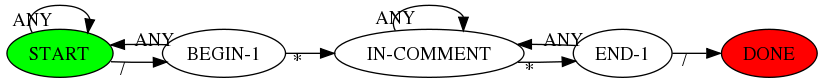
As a second example, here’s the transition diagram for a simple state machine that recognizes C-style comments. It uses the #+CALL statement
#+CALL: graph-from-tables[:file ~/org/blog/state-machine.png](nodes=state-nodes[2:-1],graph=state-edges[2:-1],horiz='t) :results file
| node | label | shape | fillcolor |
|---|---|---|---|
| start | START | ellipse | green |
| b1 | BEGIN-1 | ellipse | none |
| c | IN-COMMENT | ellipse | none |
| e1 | END-1 | ellipse | none |
| d | DONE | ellipse | red |
| from | to | label |
|---|---|---|
| start | start | ANY |
| start | b1 | / |
| b1 | start | ANY |
| b1 | c | * |
| c | c | ANY |
| c | e1 | * |
| e1 | c | ANY |
| e1 | d | / |
I love how simple all this is. Just include the code (non-exported, of course) into your buffer and write the two tables and you’ve got yourself a nice diagram without having to fuss with the dot language.